

Tutorial - Build your own CO2 sensor
EduKit CO2
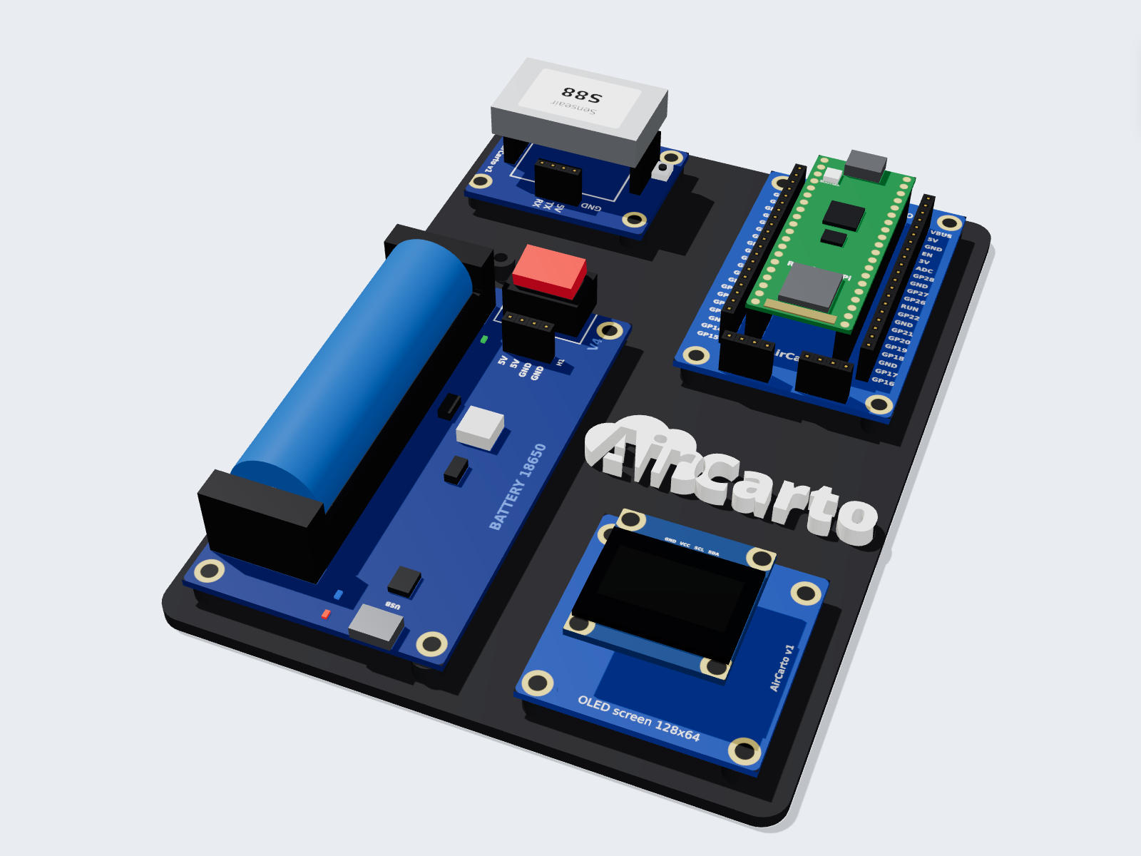
With this kit you build your own CO2 sensor to measure how stuffy a room is. It is based on a Raspberry Pi Pico 2 W and a SenseAir S88 CO2 sensor (NDIR technology). A screen shows the CO2 level in real time and tells you when to air the room.
It comes with all its boards already screwed onto a mounting plate: you only have to connect them with Dupont wires, no soldering. The kit runs on a battery and sends its readings over WiFi to the Cyan Sensor app.
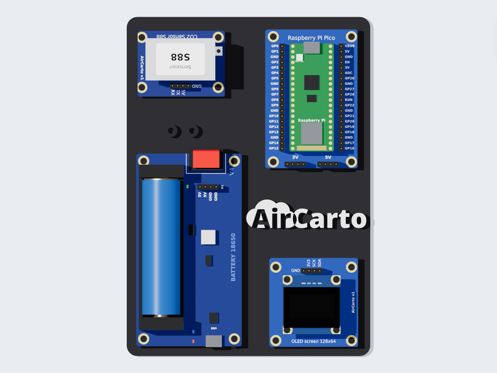
The pictures are 3D views of the kit: the boards in your hands may have a slightly different colour or details.
What is in the kit
The kit arrives already assembled: all the boards are screwed onto the plate. The battery is already in its holder, cut off by the red switch. You only have to connect the boards with the wires. In the box:
- the plate with its boards and its 18650 lithium battery (details below);
- 10 male-to-male Dupont wires (screen, S88 sensor, power);
- with the BME280 option: 4 male-to-female wires (the female end goes on the BME280).
Lay the plate in front of you with the AirCarto logo the right way up. You will find:
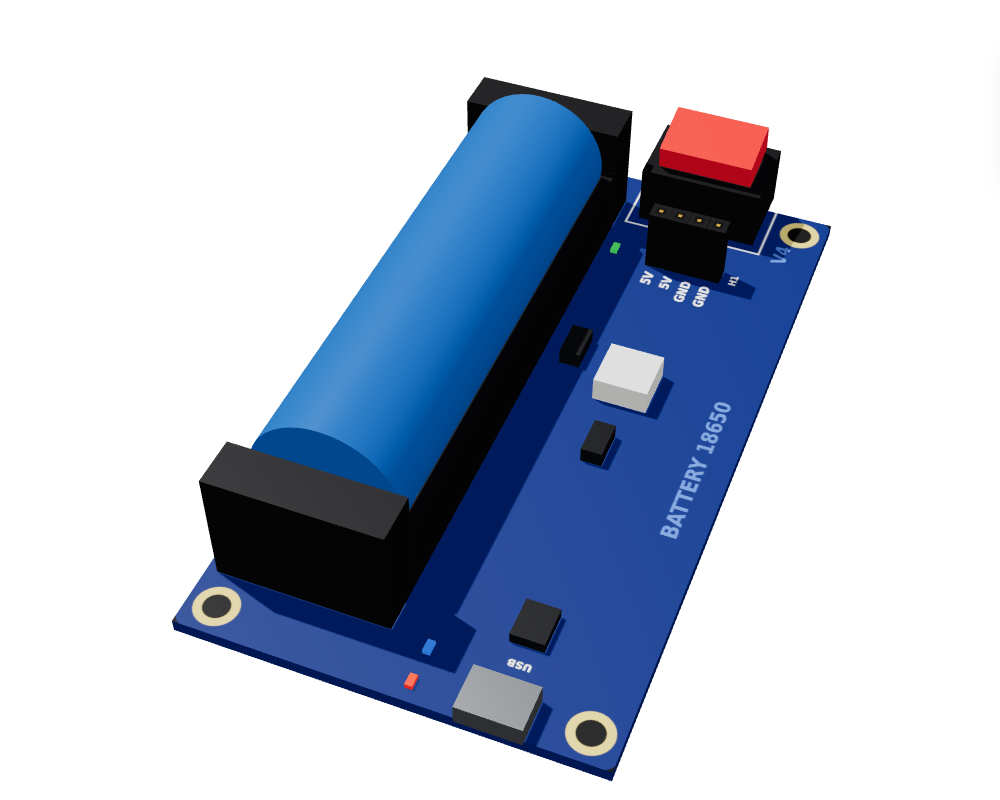
the battery board and its 18650 battery (USB charger, switch, 5V output)
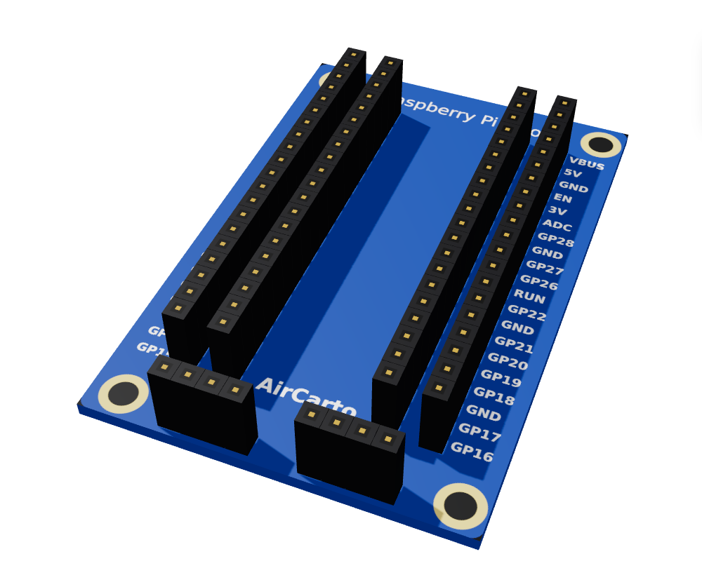
the carrier board, with its 3V and 5V rails…
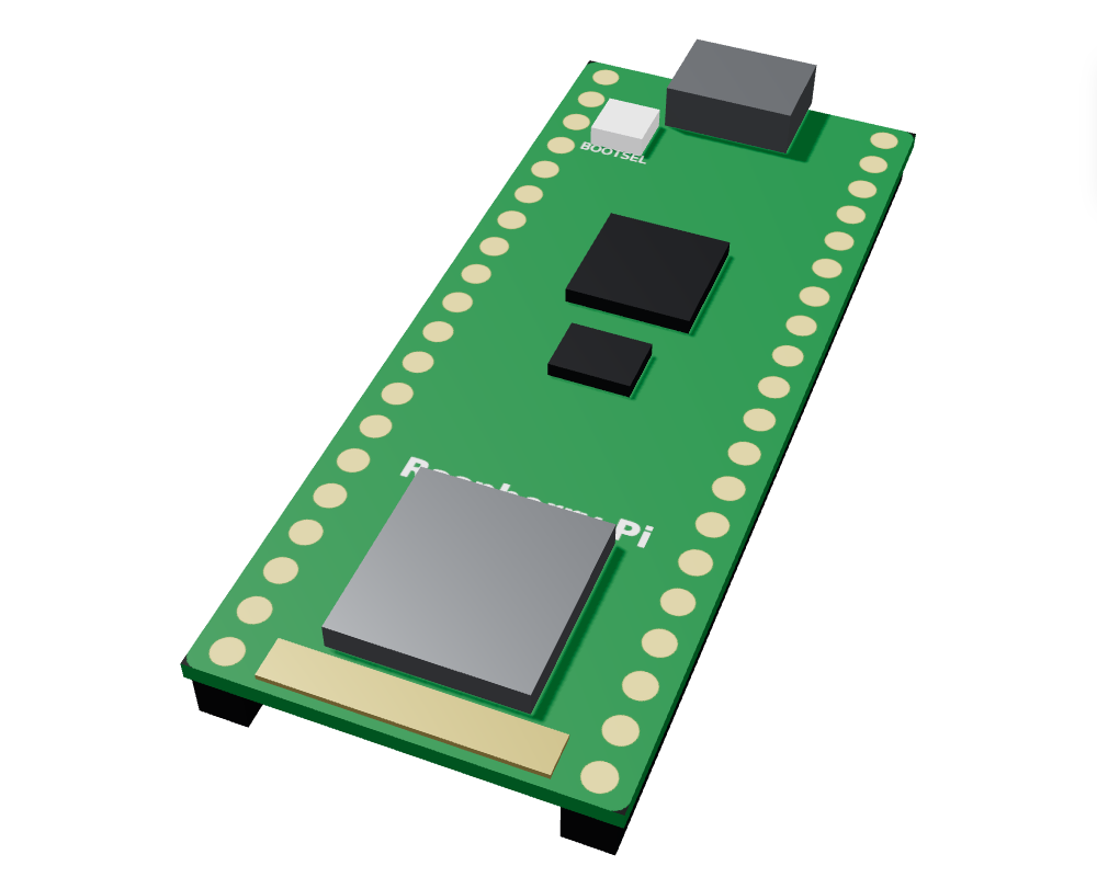
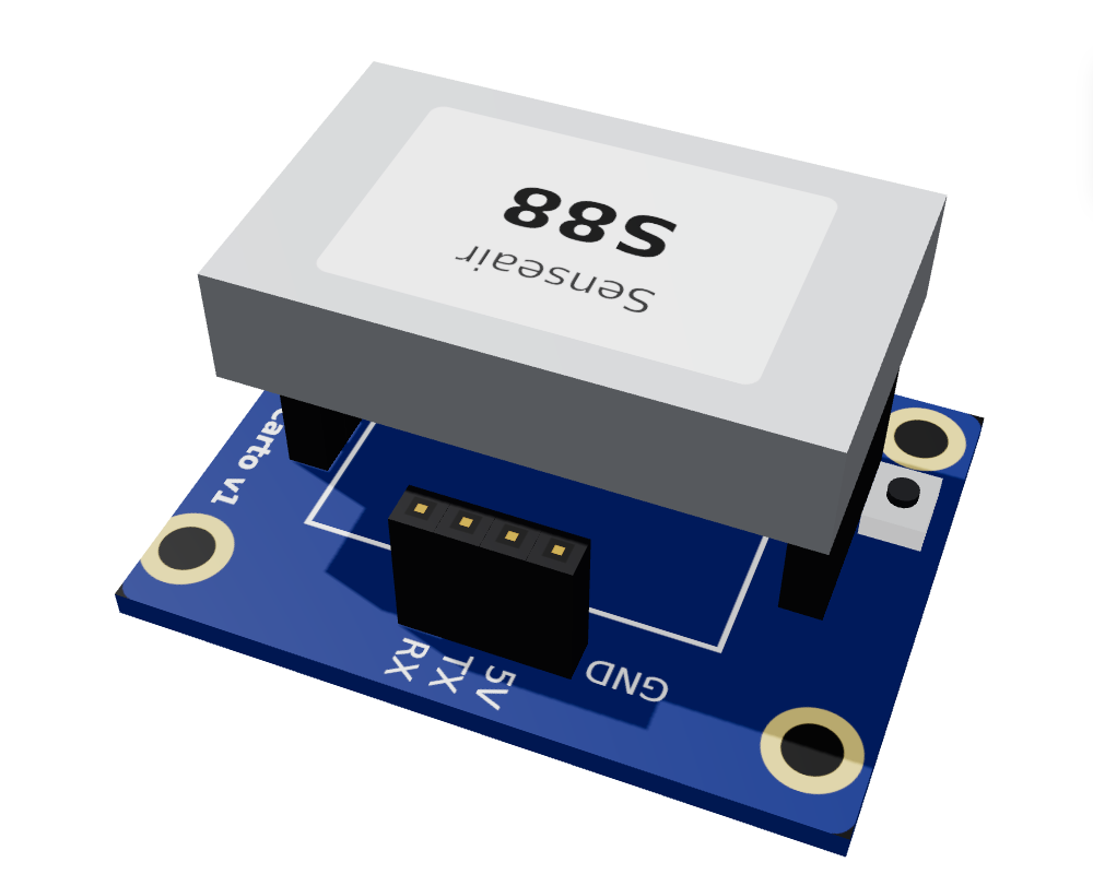
the SenseAir S88 CO2 sensor
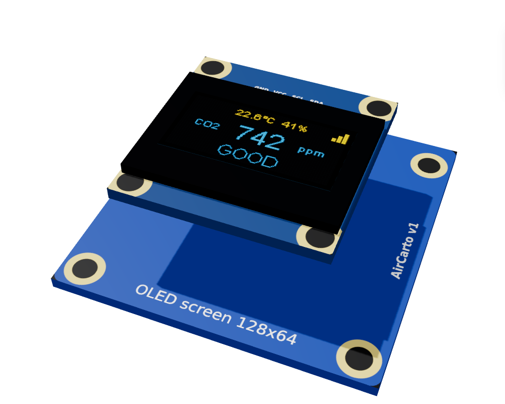
the 0.96" OLED screen
Before you start
- Red switch on O (off) during all the wiring: the battery is already in place and the switch cuts it off from the circuit. You only switch on at step 4.
- All the wires go to the Pico carrier board (top right): each pin's name is printed next to it. On each side, the outer row takes the wires; the inner row holds the Pico.
- Push each Dupont wire all the way in, straight, without forcing. Only one wire per pin.
- The 3V and 5V rails at the bottom of the carrier board work like a power strip: their 4 pins are connected together.
Suggested colours, to check your work easily:
| red | 5V | |
| orange | 3.3V | |
| black | GND (ground, the “minus”) | |
| others | data |
1. Connect the wires
For each step: the overall view, then two close-ups seen from above, on the part to connect and on the Pico carrier board. Wires already in place are greyed out. Click a picture to enlarge it.
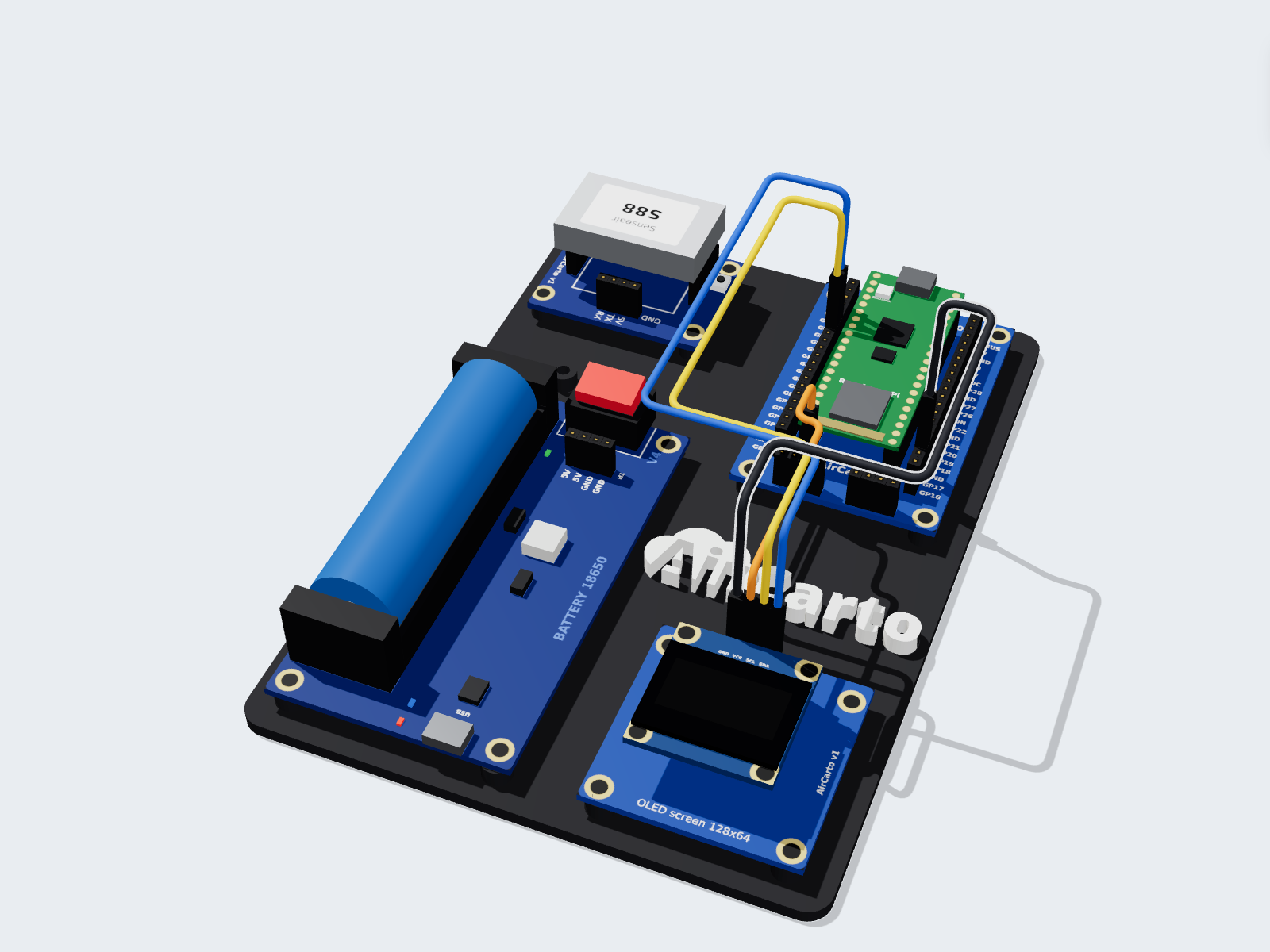
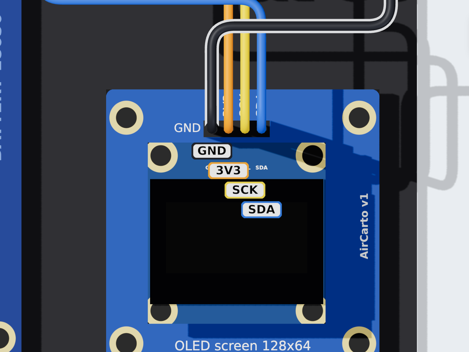
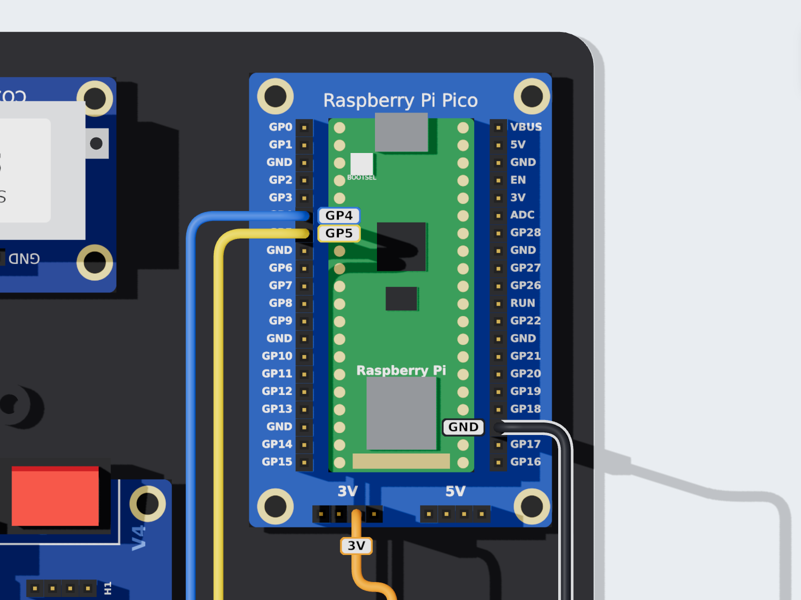
1Wire the screen (4 wires)
The screen talks to the Pico over the I2C bus: a clock wire (SCK) and a data wire (SDA). It is powered with 3.3V.
| Wire | Screen board | Pico carrier board |
|---|---|---|
| black | GND | GND right column, between GP18 and GP17 (pin 23) |
| orange | 3V3 | 3V rail |
| yellow | SCK | GP5 (pin 7) |
| blue | SDA | GP4 (pin 6) |
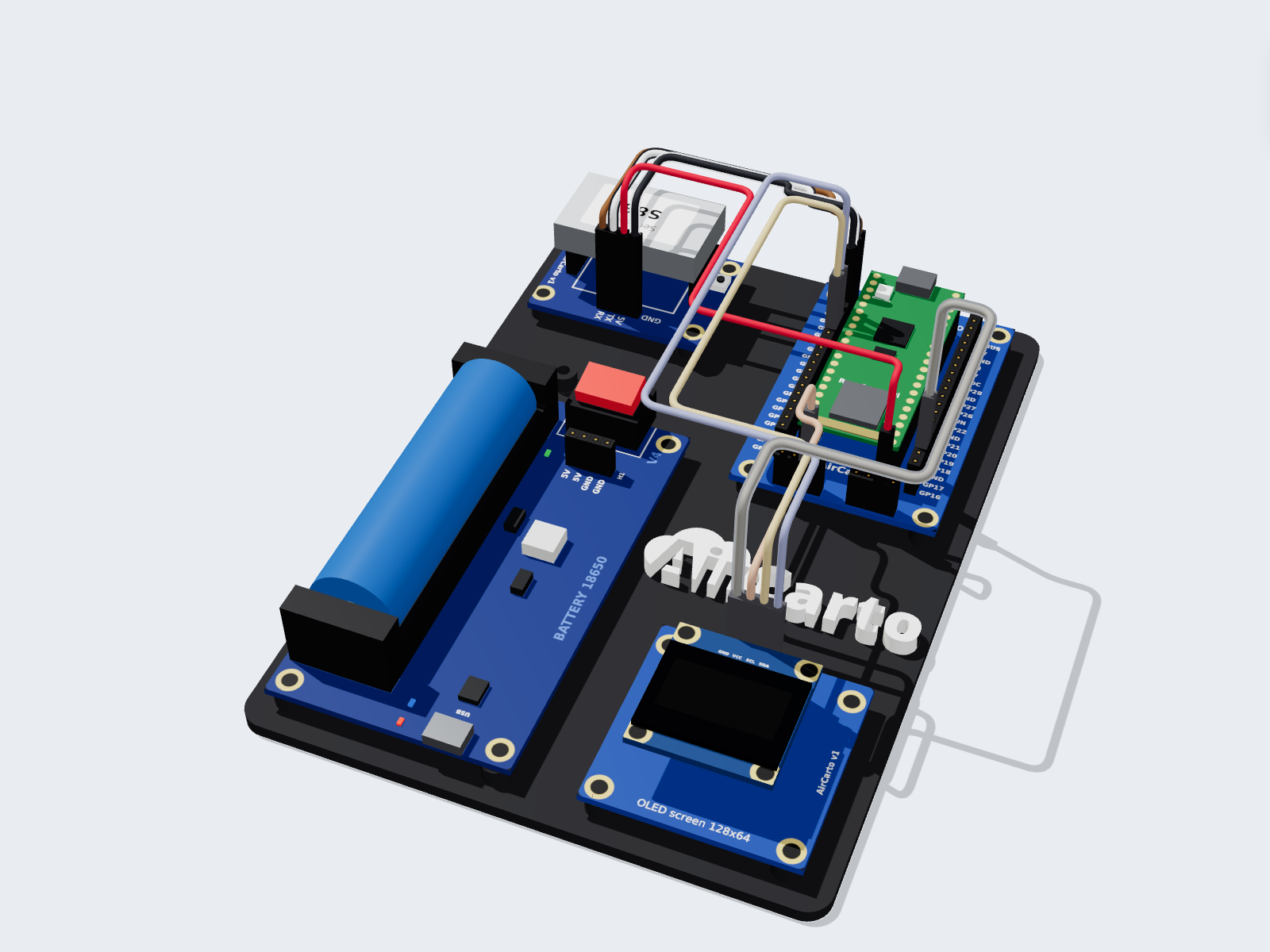
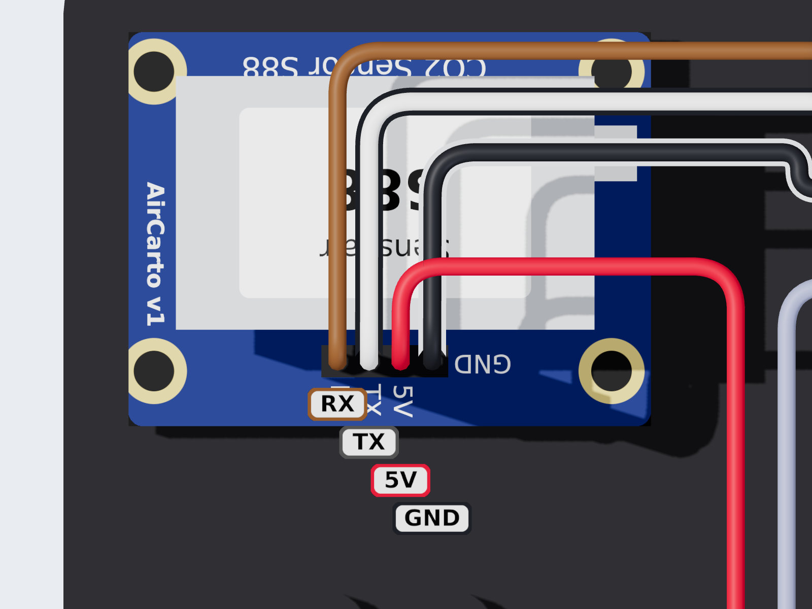
2Wire the CO2 sensor (4 wires)
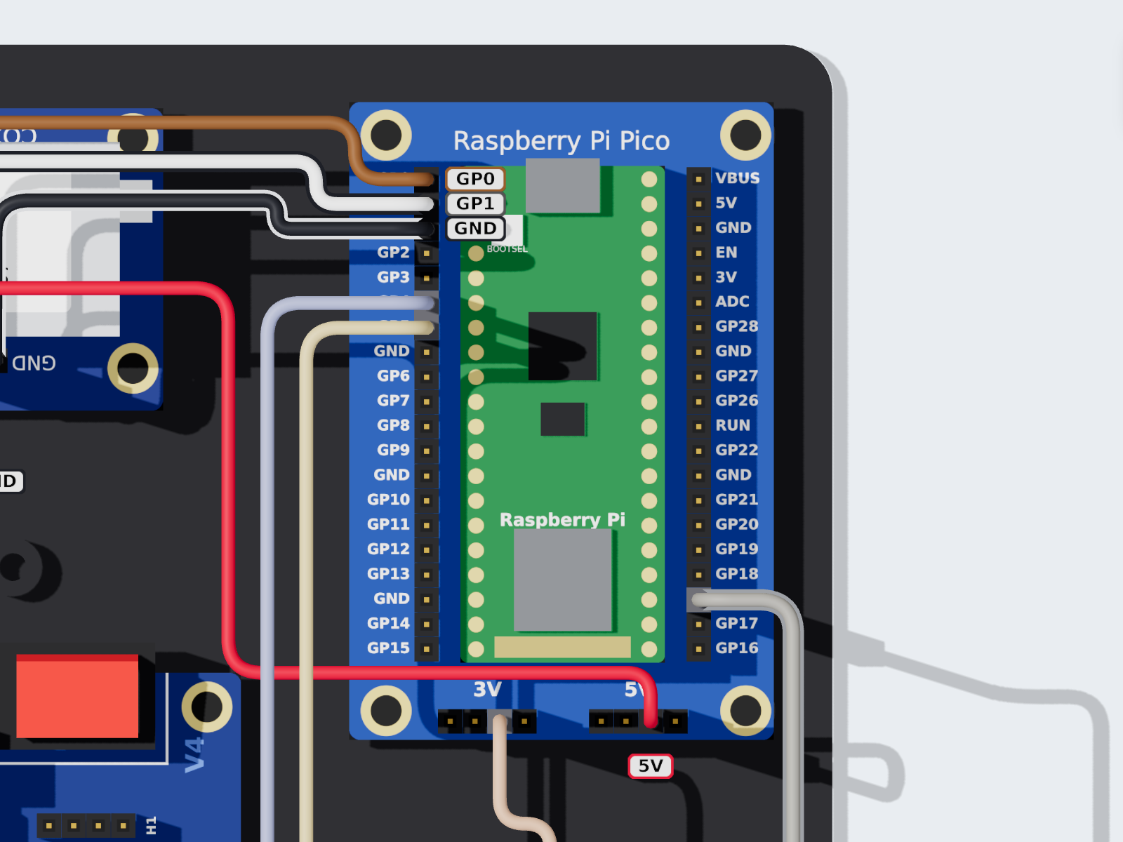
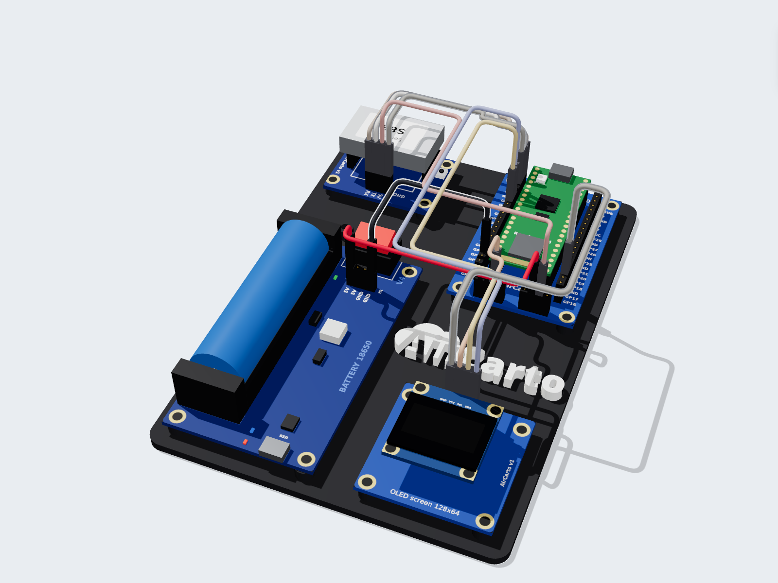
The S88 sends its readings over a serial link (UART). The wires cross: what the sensor sends (TX) goes to the Pico's input (GP1), and what the Pico sends (GP0) goes to the sensor's input (RX). The S88 is powered with 5V.
Its board is mounted upside down on the plate: its
connector is at the bottom, and its pins read from left to right RX,
TX, 5V, GND.
| Wire | S88 sensor | Pico carrier board |
|---|---|---|
| black | GND | GND left column, below GP1 (pin 3) |
| red | 5V | 5V rail |
| white | TX | GP1 (pin 2) |
| brown | RX | GP0 (pin 1) |
3Wire the power (2 wires)
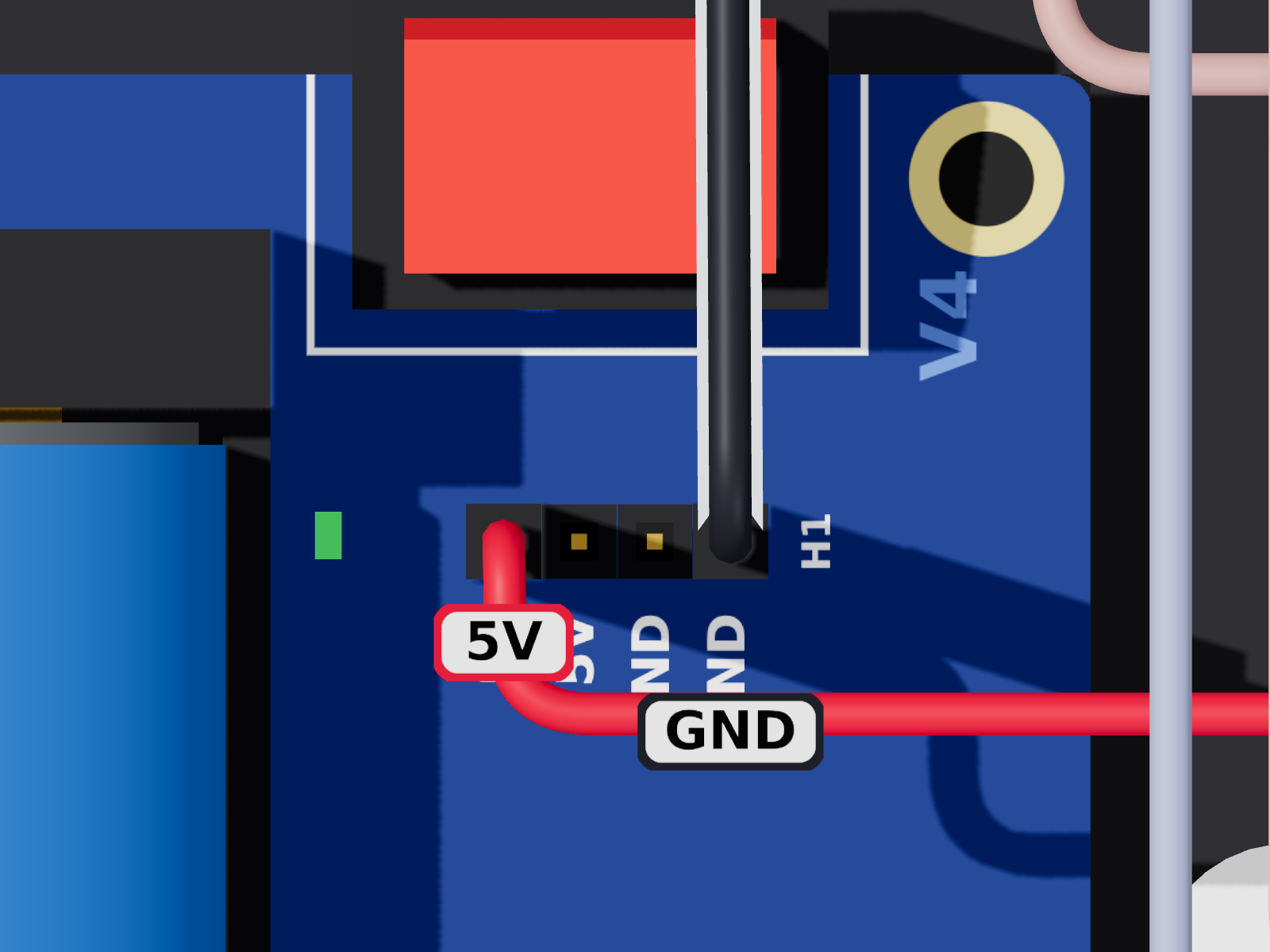
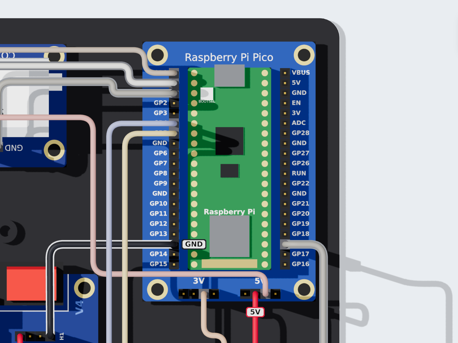
The battery board provides 5V on its H1 connector. This 5V goes to the 5V rail, which powers both the Pico and the S88 sensor.
| Wire | Battery board (H1) | Pico carrier board |
|---|---|---|
| red | 5V | 5V rail |
| black | GND | GND left column, below GP13 (pin 18) |
2. Start it up
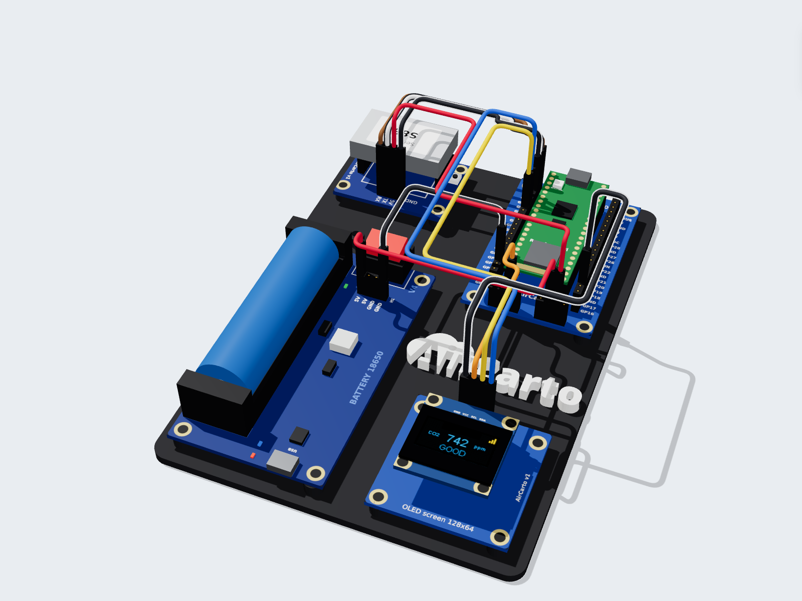
4Switch on
Flip the switch to I. The screen lights up and shows the CO2 level in ppm, with “GOOD” below 800 ppm and “VENTILATE” above. The sensor needs about a minute to give stable readings.
The screen shows “Wiring incorrect”? The Pico receives nothing from the sensor: check step 2 again.
5WiFi setup with Cyan Sensor
 Cyan Sensor
The free app for AirCarto sensors
On first start, the kit knows no WiFi network: it keeps showing the CO2
level (crossed-out network icon) and advertises itself over Bluetooth as
EduKit-….
- Install the Cyan Sensor app on a phone: App Store (iPhone) or Google Play (Android). Turn Bluetooth on.
- The EduKit appears in the list of nearby sensors: select it.
- Choose the WiFi network and type its password. The screen shows “App connected”, then “WiFi connection”, then the result.
Once connected, WiFi signal bars appear at the top right of the screen and the average CO2 level is sent every minute: you can follow it remotely in the app.
6Test the sensor
Breathe gently on the S88 sensor (top left). Within seconds the value climbs well above 1000 ppm and the screen switches to “VENTILATE”, then it slowly comes back down to the room's level.
Outdoor air contains about 420 ppm of CO2. In a closed, occupied classroom the value can go above 1500 ppm in less than an hour: time to open the windows.
Option: BME280 sensor
It adds temperature and humidity at the top of the screen, and also sends the pressure.
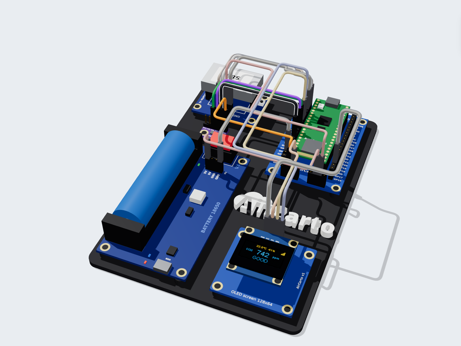
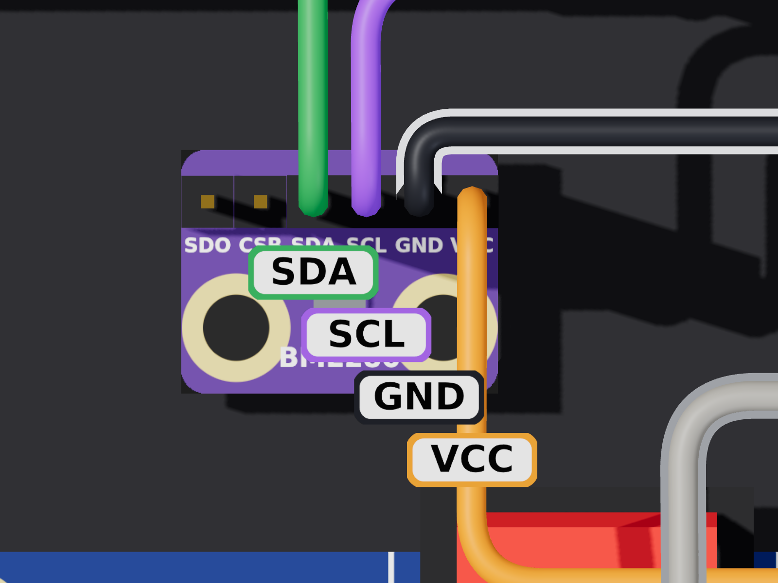
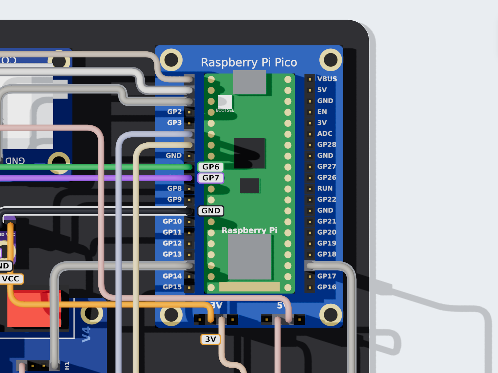
+Wire the BME280 (4 wires)
Switch on O. The BME280 sits on the left, below the S88 sensor, pins
facing up (if it is not on the plate yet, screw it onto its two small posts). It uses a
second I2C bus, separate from the screen's. The SDO and CSB
pins stay free.
| Wire | BME280 | Pico carrier board |
|---|---|---|
| orange | VCC | 3V rail |
| black | GND | GND left column, below GP9 (pin 13) |
| purple | SCL | GP7 (pin 10) |
| green | SDA | GP6 (pin 9) |
After a restart, temperature and humidity appear at the top of the screen
(for example 22.6°C 41%). Without a BME280 the EduKit works normally.
Do not mix it up with the very similar BMP280, which does not measure humidity.
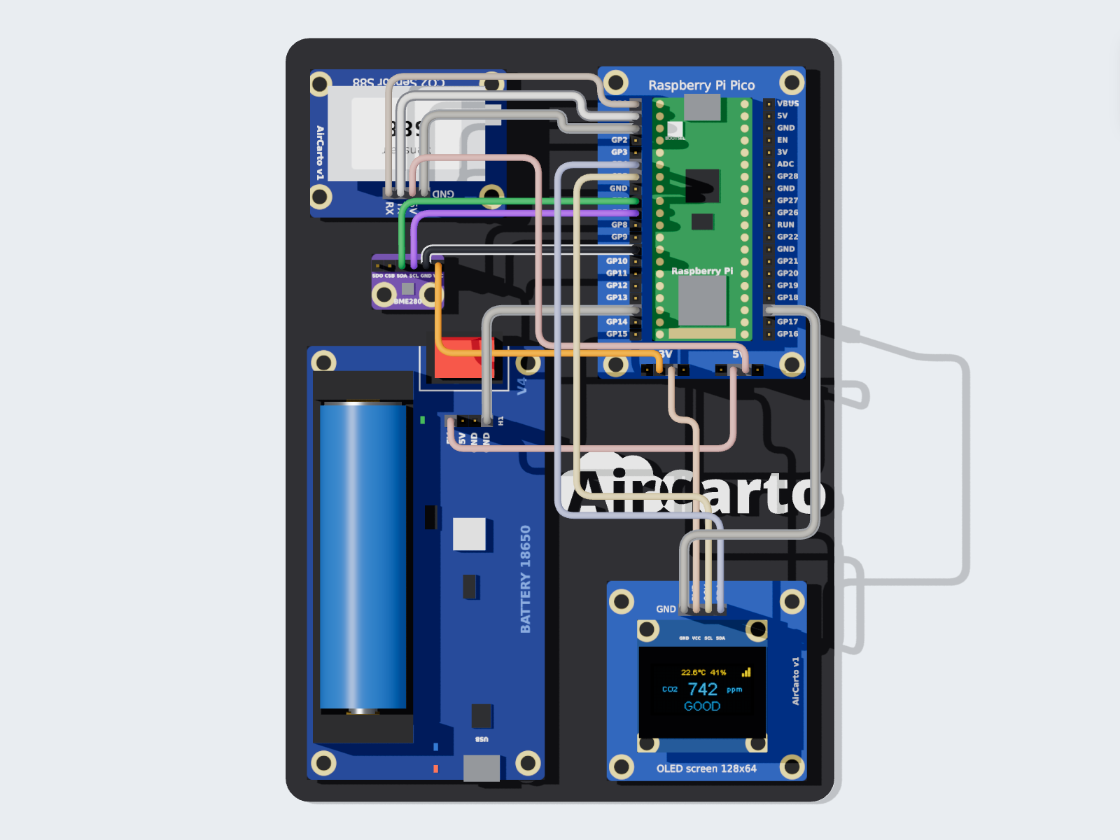
Wiring diagram
If in doubt, here is the complete wiring seen from above (with the BME280), and the detailed wiring diagram.
CO2 levels
Guidelines to interpret the readings:
The EduKit screen shows “GOOD” below 800 ppm and “VENTILATE” from 800 ppm, the threshold recommended by the French High Council for Public Health (HCSP).

Teaching resource - L'air et Moi (in French)
The French association L'air et Moi teaches children about air quality through modules for teachers, parents and youth workers. Here are 7 slides (in French) from its school module about CO2 and its use as an indicator of indoor air renewal, to go with your EduKit.


Slides © L'air et Moi - reproduced with attribution. For the full module and teacher materials, see lairetmoi.org.
Frequently asked questions
Plug a micro-USB cable into the battery board socket (at the bottom of the board), using a phone charger or a computer USB port. The red LED is on while charging, the blue LED when the battery is full.
The kit can stay on while charging: it is then powered by USB and the battery charges at the same time.
An NDIR (Non-Dispersive InfraRed) sensor measures the CO2 concentration using the absorption of infrared light. CO2 absorbs infrared light at a specific wavelength (around 4.26 µm). The sensor sends an infrared beam and measures how much light is absorbed by the CO2 in the air, which gives its concentration in ppm (parts per million).
Several parts need the same power supply, but a pin only takes one wire. The rails work like a power strip:
- the 5V rail is connected to the Pico's power input (VSYS). The battery board brings 5V to it, and the S88 sensor takes its power from it;
- the 3V rail is connected to the Pico's 3.3V output. The screen and the BME280 take their power from it.
The kit only advertises over Bluetooth when it is not connected to WiFi (crossed-out network icon on the screen). If it is already online, it is set up: its readings reach the app.
If the saved network disappears, the kit looks for it for 3 minutes, then goes back to Bluetooth so you can give it another one. Turn the phone's Bluetooth on and stay within a few metres.
- red switch on O, or flat battery (charge it);
- step 3 wires (5V and GND) badly connected;
- screen wires (step 1): SCK and SDA swapped, or 3V3 not on the 3V rail;
- Pico not fully seated in its carrier board (press gently on it).
- Warm-up: after switching on, the NDIR sensor needs about a minute to give reliable readings.
- Breath or people nearby: someone leaning over the kit raises the reading. Put it at head height, away from windows and doors.
- Low battery: charge it.
Outdoors, the reading should be around 420 ppm. If it stays far from that value outside, contact us.
Questions and comments
A question about the wiring or a remark? Feel free to leave a comment.